Helical Soil Screws: Anchoring for Foundations & Earth Retention
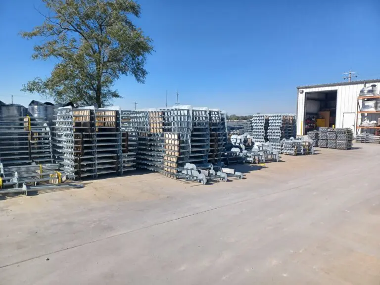
Replenish Your Supply of Soil Screws
When soil conditions require reliable stabilization and structural support, soil screws provide an efficient, high-performance solution for both temporary and permanent applications. Intech Anchoring Systems offers engineered soil screw solutions designed to meet the demands of modern construction, excavation, and earth retention projects. With fast installation, predictable performance, and minimal environmental disruption, our soil screws are trusted by engineers and contractors nationwide for a wide range of geotechnical applications.
Call 844-244-7319 today to speak with an expert about soil screw systems for your next project.

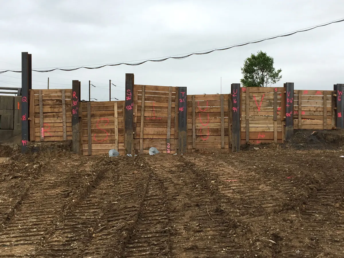
Reliable Ground Support for Complex Environments
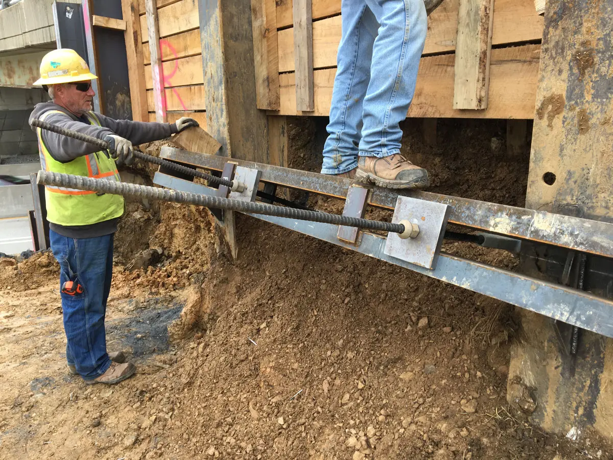
Soil screws are continuously threaded steel elements installed into the ground to provide reinforcement for excavations, slopes, retaining walls, and other earth-retaining systems. Acting as passive structural elements, they stabilize soil by transferring loads into deeper, more competent layers. This method delivers reliable, long-term stability without the need for large-scale excavation or heavy equipment.
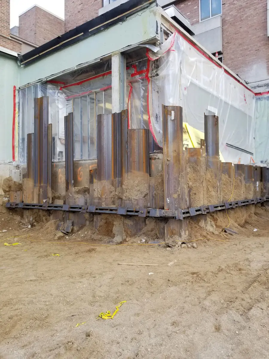
Intech Anchoring Systems supplies soil screws engineered for strength, precision, and efficiency. Our systems are manufactured from high-strength steel with corrosion-resistant coatings, designed to perform in a variety of soil conditions including clay, sand, and weathered rock. Because installation involves minimal vibration and displacement, soil screws are ideal for projects near existing structures, utilities, or sensitive environments.
From pre-construction planning through final testing, Intech Anchoring Systems supports every step of the process to ensure your project’s success.
Benefits of Soil Screws
Soil screws provide numerous advantages over traditional shoring or tieback systems. Their ease of installation and reliable performance make them a preferred choice for contractors seeking efficient and cost-effective ground stabilization.
Key benefits include:
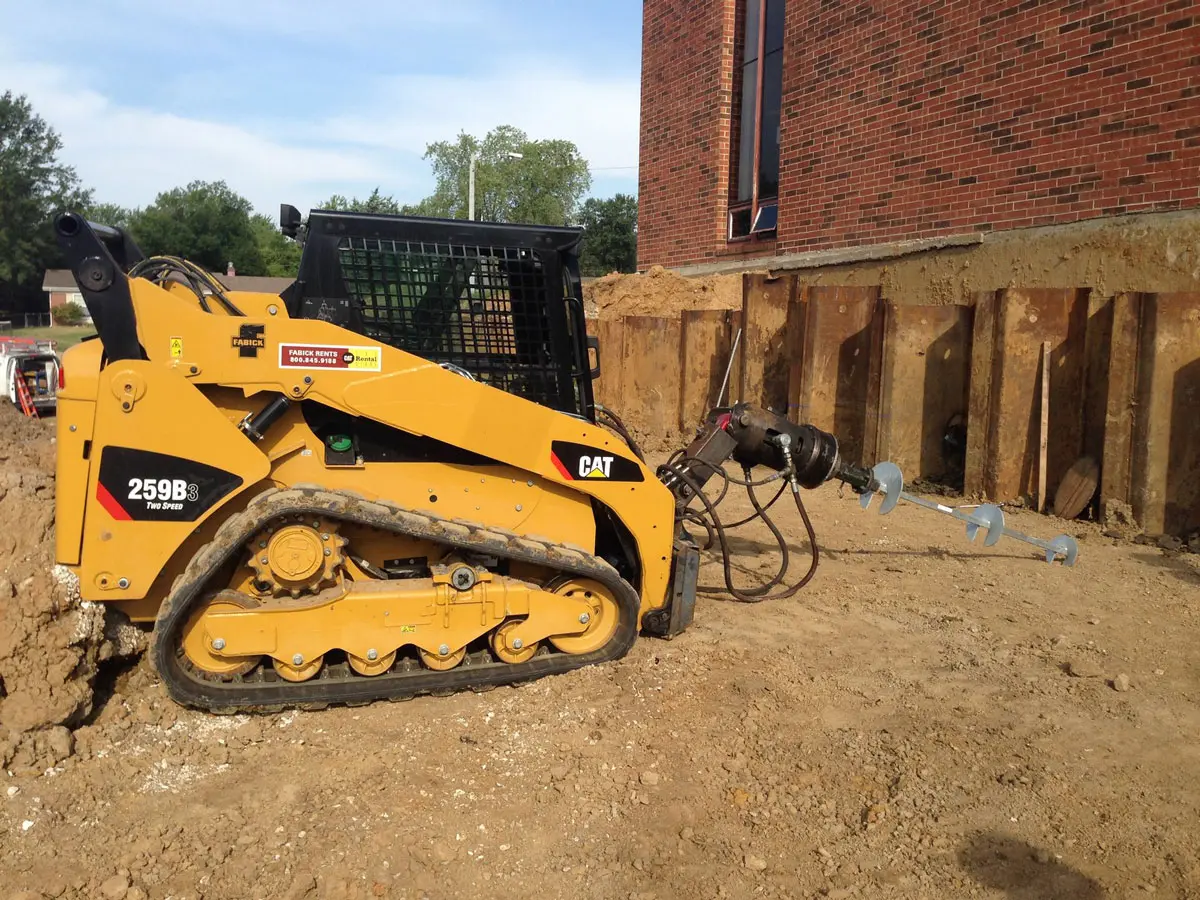
- Fast installation: Soil screws can be installed quickly using compact equipment, reducing project timelines.
- Low vibration and noise: Ideal for urban, residential, or environmentally sensitive sites.
- Versatility: Suitable for both temporary and permanent earth retention systems.
- Predictable performance: Torque-to-capacity correlation allows accurate load verification during installation.
- Minimal site disturbance: Requires no casing or grouting, reducing cleanup and environmental impact.
- Cost efficiency: Reduces labor, material, and mobilization costs compared to drilled or grouted anchors.
With Intech Anchoring Systems, you gain access to reliable soil stabilization solutions engineered for strength and precision in any environment.
Survey Your Soil Before Installing Ground Screws
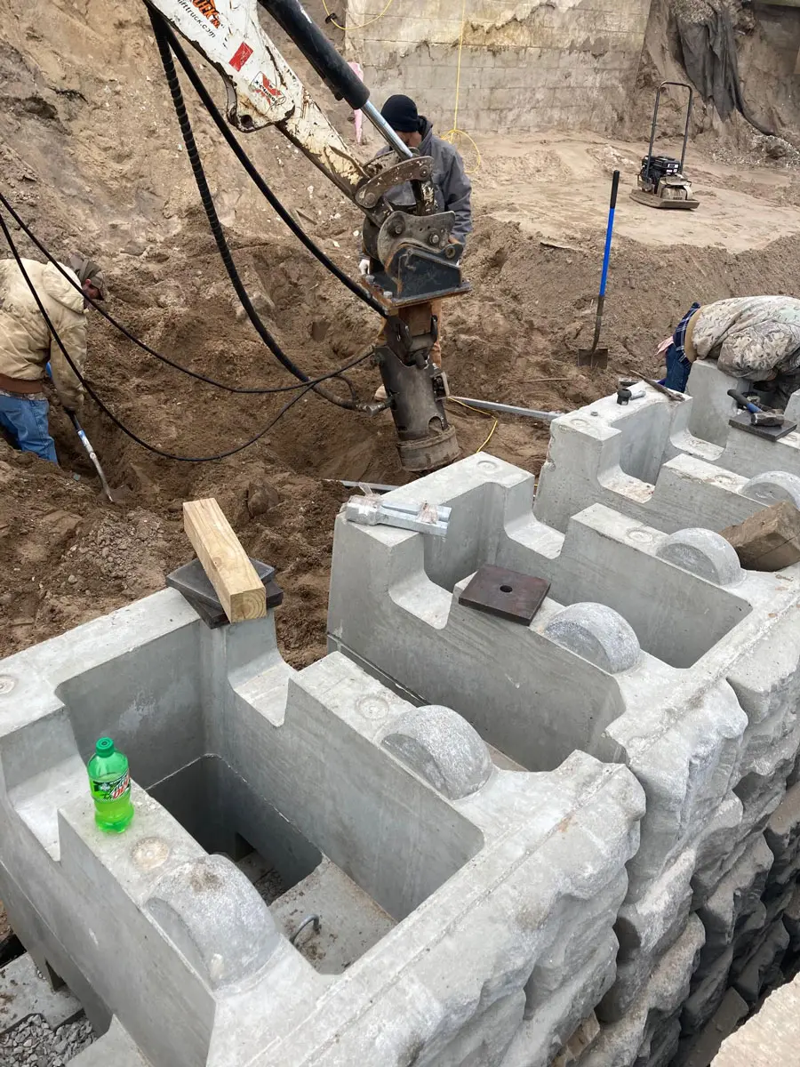
The Soil Screw Installation Process
The installation of soil screws is straightforward yet highly controlled to ensure accuracy and performance. Intech Anchoring Systems partners with engineers and contractors to provide comprehensive guidance and technical support throughout the process.
- Project assessment: Our team reviews soil reports, design loads, and site constraints to determine optimal screw type and layout.
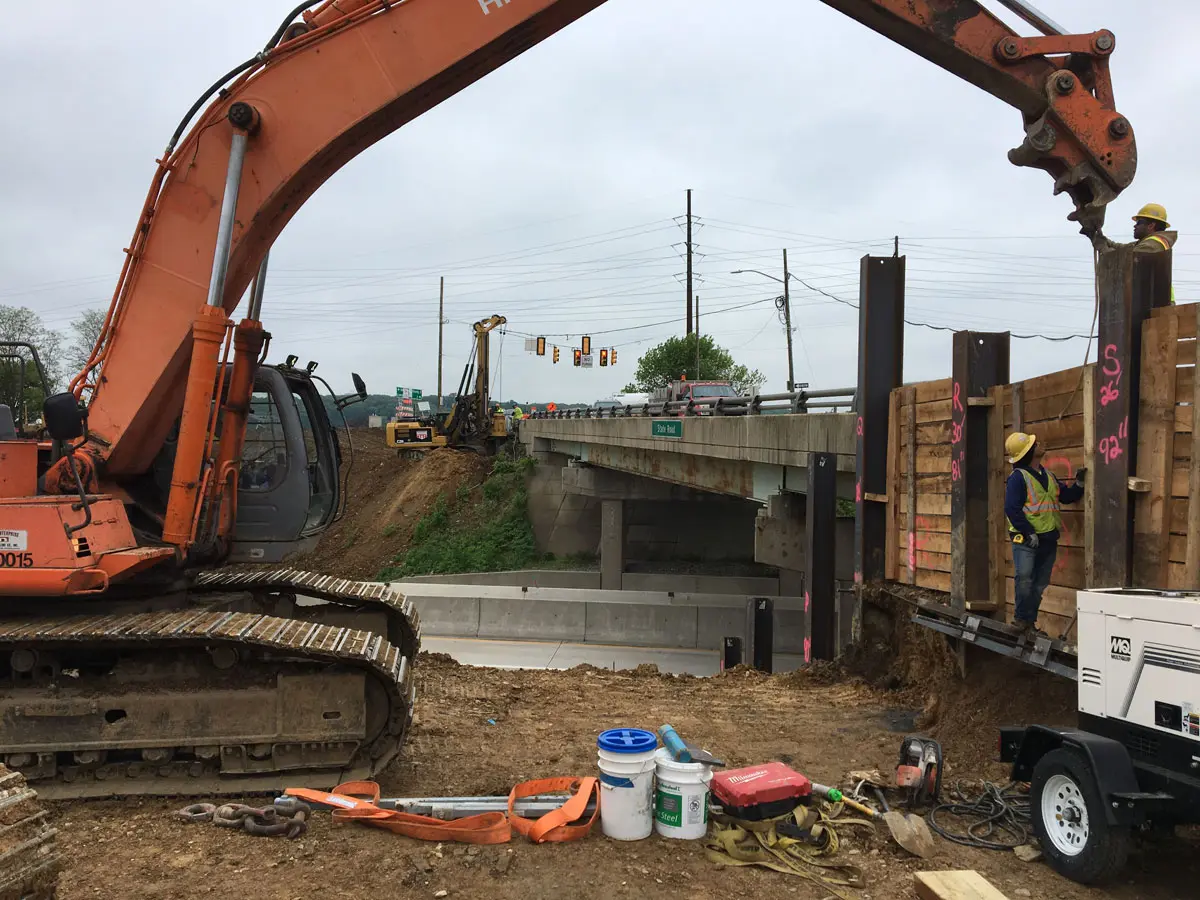
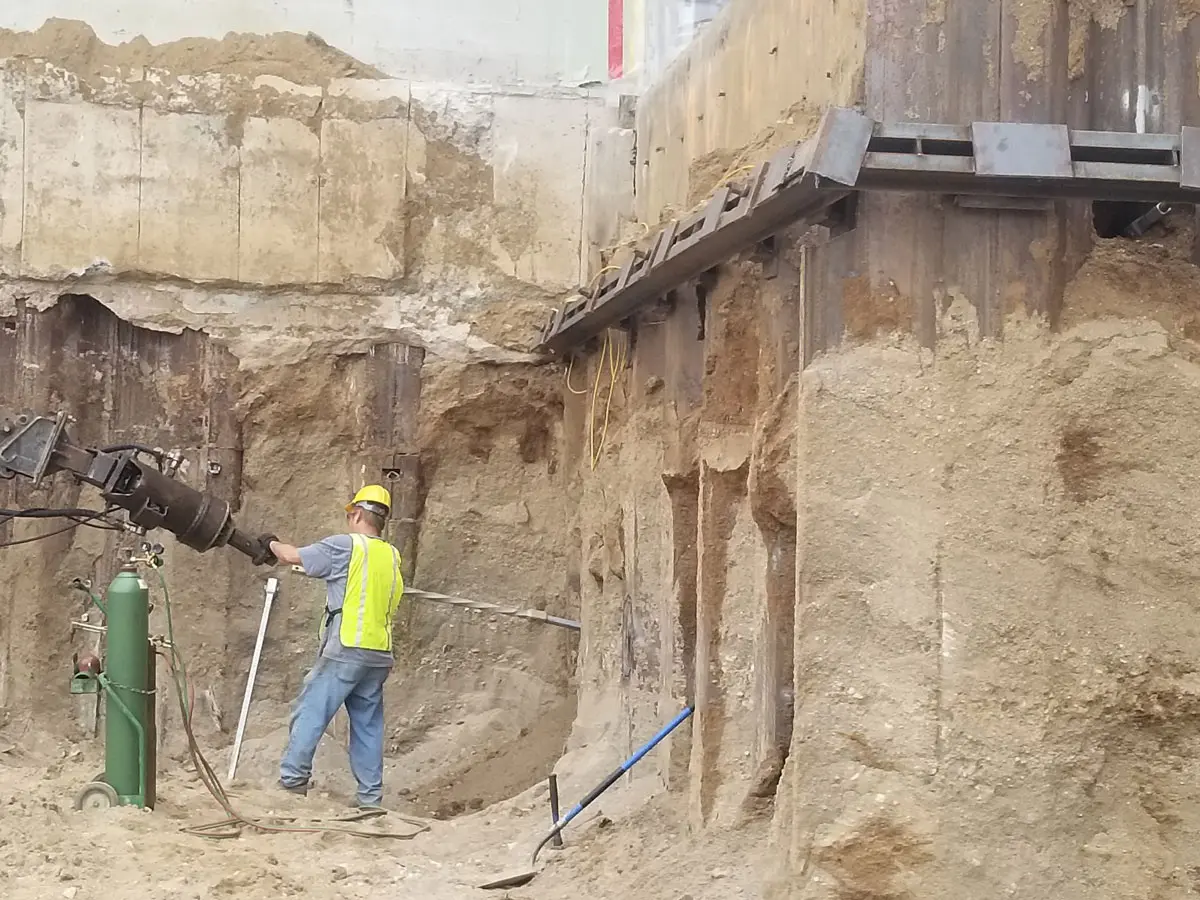
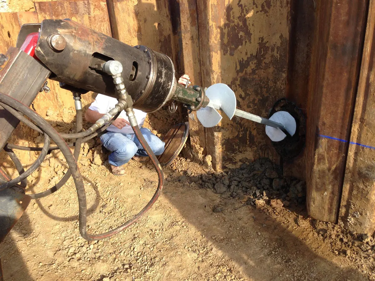
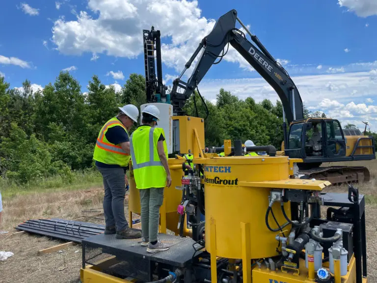
- Installation: Soil screws are advanced into the ground using rotary drilling equipment until the target torque is achieved, ensuring proper load-bearing capacity.
- Verification: Torque readings are continuously monitored and recorded to verify design compliance.
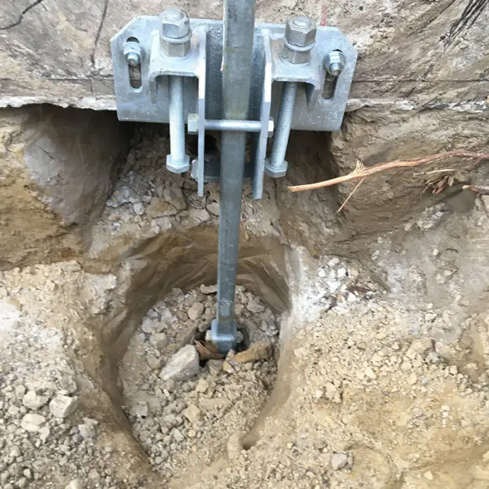
- Connection and finishing: Soil screws are fitted with face plates, nuts, or shotcrete reinforcement, depending on the project’s structural design.
- Inspection: Final inspections confirm alignment, capacity, and corrosion protection for long-term performance.
This controlled process ensures every soil screw installation meets engineering standards and project specifications.
Efficient Penetrators For Earth Reinforcement
Intech Anchoring Systems supports a full range of services and components related to soil screw design and installation, including:
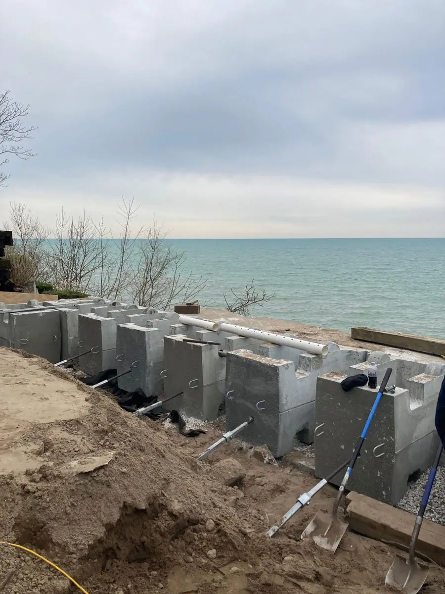
- Slope stabilization and landslide repair
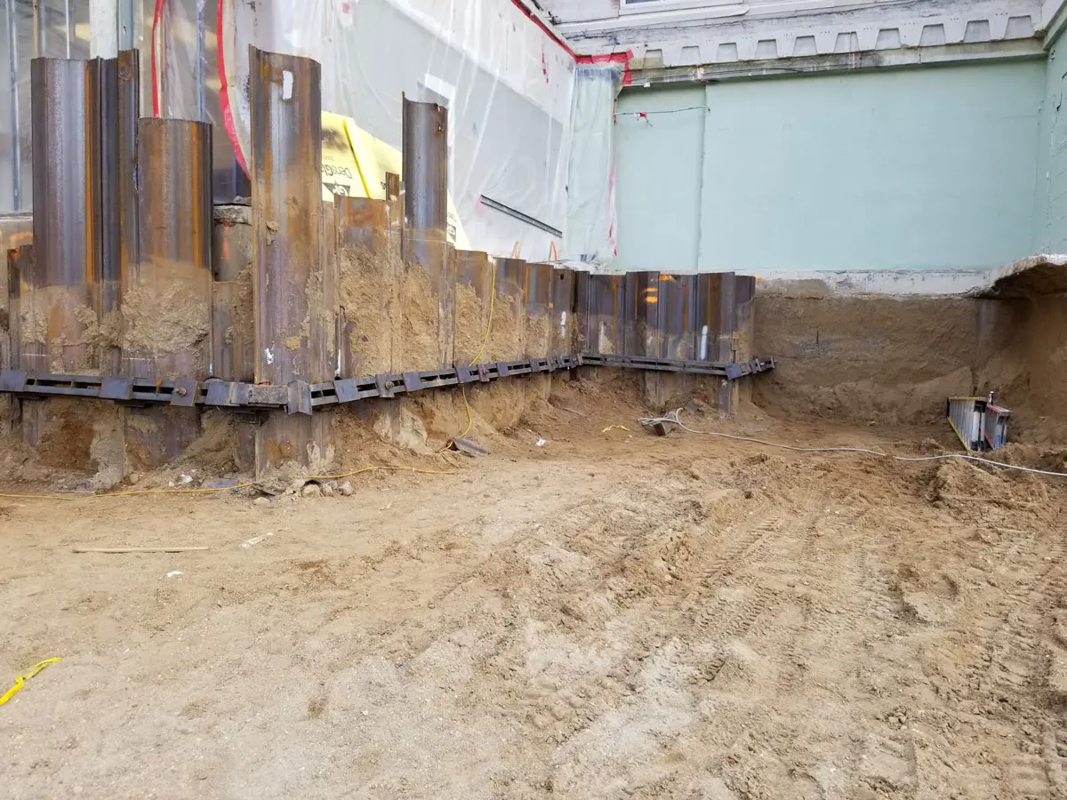
- Retaining wall and excavation shoring support
- Temporary earth retention for construction projects
- Foundation reinforcement and soil nail walls
- Onsite load testing and engineering verification
- Design assistance and specification development
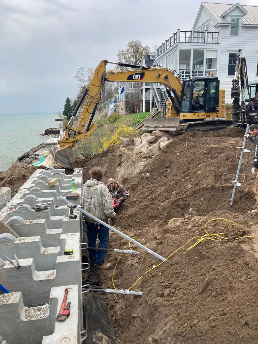
Applications for Soil Screws
Soil screws are used in diverse industries where ground stability is essential. They are an effective solution for projects that require secure earth retention in challenging or constrained environments. Common applications include:
- Infrastructure and transportation projects
- Bridge abutments and roadway cut stabilization
- Basement excavations and deep foundation support
- Commercial building sites and retaining structures
- Energy and utility installations
Because they can be installed in virtually any orientation and in most soil types, soil screws offer unparalleled flexibility for engineers and contractors seeking efficient, non-disruptive solutions.
Find Installation Equipment For Soil Screws
FAQs About Soil Screws
What is the difference between a soil screw and a soil nail?
While both systems reinforce soil, soil screws are installed by torqueing a threaded steel element into the ground, whereas soil nails are typically driven or grouted. Soil screws offer faster installation and immediate load-bearing capability.
How deep can soil screws be installed?
Installation depth depends on soil conditions and design requirements but typically ranges from 10 to 50 feet. Deeper installations are possible for projects requiring additional stability.
Are soil screws reusable?
Yes. For temporary shoring or excavation support, soil screws can often be removed and reused on future projects, depending on design and condition.
Can soil screws be used in rock or dense soils?
Yes. With appropriate pilot holes and equipment, soil screws perform effectively in dense, granular, or weathered rock formations.
How do soil screws compare to traditional tieback anchors?
Soil screws require less equipment, produce minimal vibration, and offer a faster, cleaner installation process. They are also more adaptable to confined or low-access job sites.
Why Deep Foundation Contractors Choose Intech Anchoring Systems
Intech Anchoring Systems is a leading provider of geostructural and foundation solutions engineered to perform in demanding environments. Our expertise, product quality, and dedication to service make us a trusted partner for contractors and engineers nationwide.
Here’s why industry professionals choose Intech Anchoring Systems:
- Proven performance: Our soil screws are field-tested and designed for consistent reliability under varied conditions.
- Engineering support: We collaborate with design teams to provide custom solutions tailored to each project.
- Comprehensive product line: From soil screws to helical anchors and micropiles, we offer complete solutions for foundation and stabilization needs.
- Onsite training and guidance: We provide hands-on support to ensure proper installation and verification.
- Straightforward Pricing: Transparent, competitive pricing for every system and service we offer.
Whether your project involves temporary excavation support or long-term slope stabilization, our solutions deliver lasting performance and peace of mind.
Contact Intech Anchoring Systems Today for Soil Screw Solutions
When your project requires reliable ground reinforcement, trust the experts at Intech Anchoring Systems. Our soil screws provide a proven method for stabilizing soil and supporting earth retention systems safely and efficiently. With decades of experience, technical expertise, and field-proven systems, we help contractors and engineers achieve the best results, on time and within budget.
Call Intech Anchoring Systems today at 844-244-7319 to discuss soil screw solutions for your next construction project or request detailed specifications and design assistance.